Variable Frequency Drive Basics (Working Principle)
Variable Frequency Drive (VFD) Basic Configuration
The basic configuration of a variable frequency drive is as follows.

Fig. 1 Basic configuration of variable frequency drive
Each part of a variable frequency drive has the following function.
The converter part consists of the following parts as following figure shows:
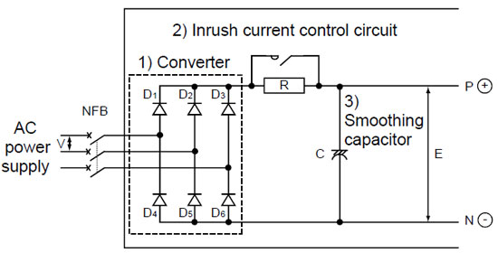
Fig. 2 Converter part
Method to create DC from AC (commercial) power supply
A converter is a device to create the DC from the AC power supply. See the basic principle with the single-phase AC as the simplest example. Fig. 3 shows the example of the method to convert the AC to the DC by utilizing a resistor for the load in place of a smoothing capacitor.
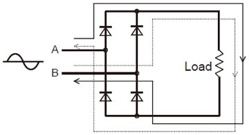
Fig. 3 Rectifying circuit
Diodes are used for the elements. These diodes let the current flow or not flow depending on the direction to which the voltage is applied as Fig. 4 shows.

Fig. 4 Diode
This diode nature allows the following: When the AC voltage is applied between A and B of the circuit shown in Fig. 3, the voltage is always applied to the load in the same direction shown in Table 1.
Table 1 Voltage applied to the load

That is to say, the AC is converted to the DC. (To convert the AC to the DC is generally called rectification.)

Fig. 5 (Continuous waveforms of the ones in Table 1)
For the three-phase AC input, combining six diodes to rectify all the waves of the AC power supply allows the output voltage as shown in Fig. 6.
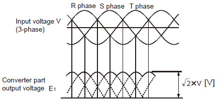
Fig. 6 Converter part waveform
Input current waveform when capacitor is used as load
The principle of rectification is explained with a resistor. However, a smoothing capacity or is actually used for the load. If a smoothing capacitor is used, the input current waveforms become not sine waveforms but distorted waveforms shown in Fig. 7 since the AC voltage flows only when it surpasses the DC voltage.
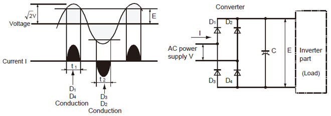
Fig. 7 Principle of converter
Inrush current control circuit
The basic principle of rectification is explained with a resistor. However, a smoothing capacitor is actually used for the load. A capacitor has a nature to store electricity. At the moment when the voltage is applied, a large inrush current flows for charging a capacitor.
To prevent rectifying diodes from being damaged by this large inrush current, make a forcible series connection to capacitors for approximately 0.05 second from the power on to control the inrush current value. After that, short the both ends of these resistors with a magnetic switch to configure a resistor-bypassed circuit.
This circuit is called an inrush current control circuit.

Fig. 8 Inrush current
Principle of smoothing circuit operation
The smoothing circuit creates the DC voltage E2 with little pulsation from the rectified DC voltage E1 using a smoothing capacitor.

Fig. 9 DC smoothed waveform
Principle of Inverter Operation
Method to create AC from DC
An inverter is a device to create the AC from the DC power supply. See the basic principle with the single-phase DC as the simplest example. Fig. 10 shows the example of the method to convert the DC to the AC by utilizing a lamp for the load in place of a motor.
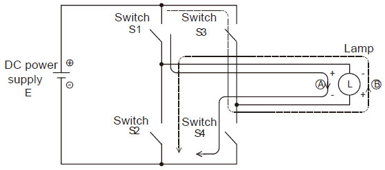
Fig. 10 Method to create AC
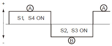
When four switches, S1 to S4, are connected to the DC power supply, S1 and S4 and also S2 and S4 are respectively paired and the pairs are alternatively turned ON and OFF, the AC flows as shown in Fig 11.
Method to change frequency
The frequency changes by changing the period to turn ON and OFF the switches S1 to S4. For example, if the switches S1 and S4 are turned ON for 0.5 second and S2 and S3 for 0.5 second and this operation is repeated, the AC with one alternation per second, i.e., the AC with a frequency of 1[Hz] is created.
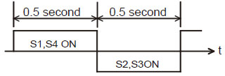
Fig. 12 1Hz AC waveform
Generally, if S1/S4 and S2/S3 are respectively turned ON for the same period and the total time for one cycle is t0 second(s), the frequency f becomes f=1/t0 [Hz].

Fig. 13 Frequency
Method to change voltage
The voltage changes by turning ON and OFF the switches with a shorter period. For example, if the switches S1 and S4 are turned ON for the half period, the output voltage is E/2, half of the DC voltage E. To obtain a higher voltage, turn ON for the longer period. To obtain a lower voltage, turn ON for the shorter period.
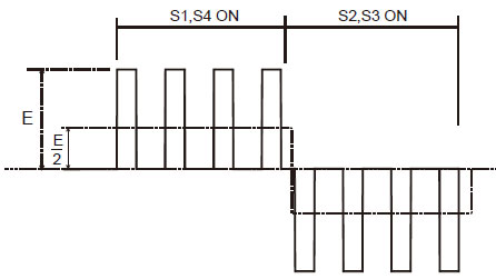
Fig. 14 Voltage waveform of E/2
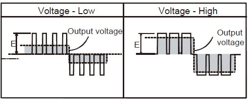
Fig. 15 Method to change voltage
This control method is generally used and called PWM (Pulse Width Modulation) since it controls pulse width. The frequency to be referenced to determine the time for pulse width is called a carrier frequency.
Three-phase AC
The basic circuit of the three-phase inverter and the method to create the three-phase AC are shown in Fig. 16 and 17.
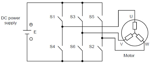
Fig. 16 3-phase inverter basic circuit
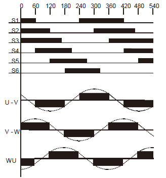
Fig. 17 Method to create 3-phase AC
To obtain the three-phase AC, connect the switches S1 to S6 to the circuit and simultaneously turn ON/OFF all the six switches at the timing shown in Fig. 17. If the order of turning ON/OFF six switches is changed, the phase order is changed between U-V, V-W and W-U and the rotation direction can be changed.
Switch element
For the switch element in the explanation above, a semiconductor called IGBT (Insulated Gate Bipolar Transistor) is used.
V/F pattern
Changing the motor speed is enabled by changing the frequency as shown in following Formula. When the output frequency of a variable frequency drive is changed, the output voltage must be changed.
The relationship between the magnetic flux (Φ), the voltage applied to a motor (V) and the frequency (F), is expressed as Φ=V/F. If the voltage is fixed (e.g. 200V) and only the frequency is decreased, the increased magnetic flux (Φ) causes the iron core to be magnetic saturation and then the increased current causes overheat and burnout.
Changing the voltage applied to a motor (V) and the frequency (F) with their relationship kept constant allows the motor output torque to be constant even if the motor speed is changed. For these two reasons, the output voltage must be controlled low when the variable frequency drive output frequency is low, and controlled high when the frequency is high.
This relationship between the output frequency and the output voltage is called V/F pattern.
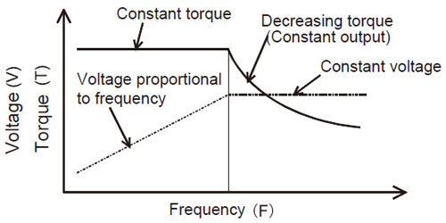
Fig. 18 V/F pattern and motor output torque
Regenerative Brake
When the motor speed surpasses the VFD output frequency (speed command from a VFD) such as the situation where an elevator goes down, a motor works as a generator and the generated electricity (energy) returns to a variable frequency drive. This status is called regeneration.
When the electricity returns to a variable frequency drive, the DC voltage of the variable frequency drive (Fig. 19 E1) increases. If this DC voltages surpasses a certain specified value (370VDC for 200V class), rectifying diodes or IGBT of the variable frequency drive part are damaged. To prevent this, insert a resistor and a power capacitor for a switch element in series in the DC voltage circuit (between P and N) as shown in Fig. 19. This prevents the DC voltage increase by turning ON the power transistor to consume the current as heat when the DC voltage surpasses a certain specified value. See Fig. 20. This resistor is called a regenerative brake resistor and this power capacitor a regenerative brake capacitor.
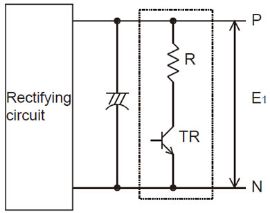
Fig. 19 Regenerative brake circuit
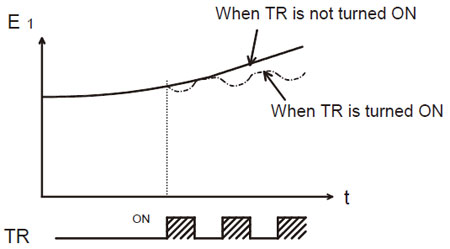
Fig. 20 DC voltage (between P and N)
For a large capacity variable frequency drive that needs a large regenerative brake resistor, the power return system, which returns the regenerative energy to the power supply side, is adopted to prevent the heat influence to the ambiance.
Control
Difference between general-purpose VFD and vector VFD
Although the same main circuit is used between a general-purpose variable frequency drive (VFD) and a vector variable frequency drive, the following differences exist in outline according to the used control circuit or the presence/absence of an encoder, which depends on the applied motor.
Table. 2 Difference between general-purpose VFD and vector VFD
Control method
There are three basic methods to control a variable frequency drive: speed control to control the motor speed mainly with the analog voltage, position control to control the motor rotation amount with simple limit switches, a high accuracy encoder or others and torque control to control the current flowing into a motor for a constant torque value.
The detailed account is given below.
Speed control
1) Open loop control
This control method does not feed back the speed as general-purpose variable frequency drives adopt it.
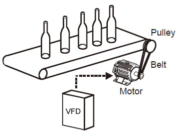 The command system is analog voltage command, which is used for many applications such as the conveyor speed control, fan wind amount control, pump flow amount control, etc. The slip at the rated torque depends on the characteristics of a motor. Approximately 3 to 5% speed fluctuation occurs. The recent variable frequency drives are resistant to temperature drifts for the digital control that allows setting the speed data internally and for the digital command (pulse train, parallel data and communication). In addition, the variable frequency drives of advanced magnetic flux vector control or real sensorless vector control are available with the speed fluctuation of 1% or less.
This speed control method is worked for almost all general-purpose variable frequency drives.
2) Closed loop control
To ensure the change of the motor speed, an encoder must be installed to detect the actual speed and feed it back to a control circuit. This method is called a closed loop control.

To detect the speed, TG (tachogenerator), encoder, etc. are used. Encoders are mostly used these days. For the closed loop control too, the analog voltage or current is used for the speed command. However, inputting pulse trains or using the digital input allows a high accuracy speed control for the draw operation or continuous speed control operation.
Position control
The position control allows not only the control of the motor speed but also the control to stop at the target stop position. There are many control methods from the simple method to stop at the target position by taking the external sensor signals into the stop signal, to the method to perform a high accuracy positioning with an encoder installed to the motor, and to the advanced method to perform a positioning to always-changing target stop positions by tracking or synchronization.
1) Open loop control
This control is used for the applications that do not need high accuracy for stop. The motor decelerates to stop with signals from the limit switches installed before the target stop position for deceleration command. This is the simplest and most reasonable method although the fluctuation of the deceleration points affects the stop positions in accuracy.
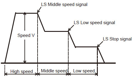
2) Semi-closed loop control
An encoder installed to a motor performs feedback. For example, a vector dedicated motor operates for the command input to a vector variable frequency drive when the feedback is looped back. At this moment, the speed command is calculated to zero the difference between the input command amount and the feedback amount for rotating the motor.
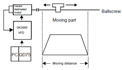
3) Full-closed loop control
This control is performed by the feedback from a linear scale or encoder installed to the machine side. Installing a linear scale or encoder to the final machine edge allows a high accuracy positioning free from backlashes or mechanical system errors. Instead, it is required to heighten the machine rigidity. This control is sometimes used for machine tools part of which requires a high accuracy control.

Torque control
The torque control indicates controlling the torque (current) output from a motor and it must be distinguished from the torque limit. However, both of them are available depending on the application. The most appropriate method should be selected. The torque control performs a control of the torque (current) against the torque command value. Therefore, the speed automatically increases when the load torque is smaller and decreases when larger. If the load torque is equal to the torque command value, both torque values are balanced and the speed becomes zero. That is to say, the motor stops. In short, the same principle as a tug of war is working.
On the other hand, the torque limit is used when a machine can be damaged for unnecessary torque to control the position or speed, when the stop is performed by pressing the machine, or when the mechanical lock is performed. For the torque control, the current flowing in the motor must be detected and controlled. Therefore, the torque control can be supported by the vector variable frequency drive or the variable frequency drive of real sensorless vector control, which perform current detection.
1) Open loop control
This control is used for the applications that do not require high torque accuracy such as an unwinding or winding axis. The analog command is generally used for the torque command. For this control, it must be taken into account that the torque accuracy (temperature drift) varies depending on the temperature and machines have losses.

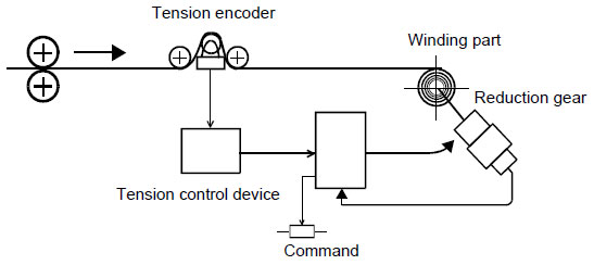
2) Closed loop control
This control is used for the applications that require high tension accuracy such as an unwinding or winding axis (for paper, film, etc.). This control feeds back the tension applied to the actual products to a tension control device.
The basic configuration of a variable frequency drive is as follows.

Fig. 1 Basic configuration of variable frequency drive
Each part of a variable frequency drive has the following function.
Converter: Circuit to change the commercial AC power supply to the DCPrinciple of Converter Operation
Smoothing circuit: Circuit to smooth the pulsation included in the DC
Inverter: Circuit to change the DC to the AC with variable frequency
Control circuit: Circuit to mainly control the inverter part
The converter part consists of the following parts as following figure shows:
- Converter
- Inrush current control circuit
- Smoothing circuit

Fig. 2 Converter part
Method to create DC from AC (commercial) power supply
A converter is a device to create the DC from the AC power supply. See the basic principle with the single-phase AC as the simplest example. Fig. 3 shows the example of the method to convert the AC to the DC by utilizing a resistor for the load in place of a smoothing capacitor.

Fig. 3 Rectifying circuit
Diodes are used for the elements. These diodes let the current flow or not flow depending on the direction to which the voltage is applied as Fig. 4 shows.

Fig. 4 Diode
This diode nature allows the following: When the AC voltage is applied between A and B of the circuit shown in Fig. 3, the voltage is always applied to the load in the same direction shown in Table 1.
Table 1 Voltage applied to the load

That is to say, the AC is converted to the DC. (To convert the AC to the DC is generally called rectification.)

Fig. 5 (Continuous waveforms of the ones in Table 1)
For the three-phase AC input, combining six diodes to rectify all the waves of the AC power supply allows the output voltage as shown in Fig. 6.

Fig. 6 Converter part waveform
Input current waveform when capacitor is used as load
The principle of rectification is explained with a resistor. However, a smoothing capacity or is actually used for the load. If a smoothing capacitor is used, the input current waveforms become not sine waveforms but distorted waveforms shown in Fig. 7 since the AC voltage flows only when it surpasses the DC voltage.

Fig. 7 Principle of converter
Inrush current control circuit
The basic principle of rectification is explained with a resistor. However, a smoothing capacitor is actually used for the load. A capacitor has a nature to store electricity. At the moment when the voltage is applied, a large inrush current flows for charging a capacitor.
To prevent rectifying diodes from being damaged by this large inrush current, make a forcible series connection to capacitors for approximately 0.05 second from the power on to control the inrush current value. After that, short the both ends of these resistors with a magnetic switch to configure a resistor-bypassed circuit.
This circuit is called an inrush current control circuit.

Fig. 8 Inrush current
Principle of smoothing circuit operation
The smoothing circuit creates the DC voltage E2 with little pulsation from the rectified DC voltage E1 using a smoothing capacitor.

Fig. 9 DC smoothed waveform
Principle of Inverter Operation
Method to create AC from DC
An inverter is a device to create the AC from the DC power supply. See the basic principle with the single-phase DC as the simplest example. Fig. 10 shows the example of the method to convert the DC to the AC by utilizing a lamp for the load in place of a motor.

Fig. 10 Method to create AC
When four switches, S1 to S4, are connected to the DC power supply, S1 and S4 and also S2 and S4 are respectively paired and the pairs are alternatively turned ON and OFF, the AC flows as shown in Fig 11.

- When the switches S1 and S4 are turned ON, the current flows in the lamp in the direction of A.
- When the switches S2 and S3 are turned ON, the current flows in the lamp in the direction of B.
Method to change frequency
The frequency changes by changing the period to turn ON and OFF the switches S1 to S4. For example, if the switches S1 and S4 are turned ON for 0.5 second and S2 and S3 for 0.5 second and this operation is repeated, the AC with one alternation per second, i.e., the AC with a frequency of 1[Hz] is created.

Fig. 12 1Hz AC waveform
Generally, if S1/S4 and S2/S3 are respectively turned ON for the same period and the total time for one cycle is t0 second(s), the frequency f becomes f=1/t0 [Hz].

Fig. 13 Frequency
Method to change voltage
The voltage changes by turning ON and OFF the switches with a shorter period. For example, if the switches S1 and S4 are turned ON for the half period, the output voltage is E/2, half of the DC voltage E. To obtain a higher voltage, turn ON for the longer period. To obtain a lower voltage, turn ON for the shorter period.

Fig. 14 Voltage waveform of E/2

Fig. 15 Method to change voltage
This control method is generally used and called PWM (Pulse Width Modulation) since it controls pulse width. The frequency to be referenced to determine the time for pulse width is called a carrier frequency.
Three-phase AC
The basic circuit of the three-phase inverter and the method to create the three-phase AC are shown in Fig. 16 and 17.

Fig. 16 3-phase inverter basic circuit

Fig. 17 Method to create 3-phase AC
To obtain the three-phase AC, connect the switches S1 to S6 to the circuit and simultaneously turn ON/OFF all the six switches at the timing shown in Fig. 17. If the order of turning ON/OFF six switches is changed, the phase order is changed between U-V, V-W and W-U and the rotation direction can be changed.
Switch element
For the switch element in the explanation above, a semiconductor called IGBT (Insulated Gate Bipolar Transistor) is used.
V/F pattern
Changing the motor speed is enabled by changing the frequency as shown in following Formula. When the output frequency of a variable frequency drive is changed, the output voltage must be changed.
Torque TM = K x Φ x I = K x (V/F) x IThe output torque of a motor is expressed as the product of the magnetic flux inside the motor (Φ) multiplied by the current flowing in the coil (I).
The relationship between the magnetic flux (Φ), the voltage applied to a motor (V) and the frequency (F), is expressed as Φ=V/F. If the voltage is fixed (e.g. 200V) and only the frequency is decreased, the increased magnetic flux (Φ) causes the iron core to be magnetic saturation and then the increased current causes overheat and burnout.
Changing the voltage applied to a motor (V) and the frequency (F) with their relationship kept constant allows the motor output torque to be constant even if the motor speed is changed. For these two reasons, the output voltage must be controlled low when the variable frequency drive output frequency is low, and controlled high when the frequency is high.
This relationship between the output frequency and the output voltage is called V/F pattern.

Fig. 18 V/F pattern and motor output torque
Regenerative Brake
When the motor speed surpasses the VFD output frequency (speed command from a VFD) such as the situation where an elevator goes down, a motor works as a generator and the generated electricity (energy) returns to a variable frequency drive. This status is called regeneration.
When the electricity returns to a variable frequency drive, the DC voltage of the variable frequency drive (Fig. 19 E1) increases. If this DC voltages surpasses a certain specified value (370VDC for 200V class), rectifying diodes or IGBT of the variable frequency drive part are damaged. To prevent this, insert a resistor and a power capacitor for a switch element in series in the DC voltage circuit (between P and N) as shown in Fig. 19. This prevents the DC voltage increase by turning ON the power transistor to consume the current as heat when the DC voltage surpasses a certain specified value. See Fig. 20. This resistor is called a regenerative brake resistor and this power capacitor a regenerative brake capacitor.

Fig. 19 Regenerative brake circuit

Fig. 20 DC voltage (between P and N)
For a large capacity variable frequency drive that needs a large regenerative brake resistor, the power return system, which returns the regenerative energy to the power supply side, is adopted to prevent the heat influence to the ambiance.
Control
Difference between general-purpose VFD and vector VFD
Although the same main circuit is used between a general-purpose variable frequency drive (VFD) and a vector variable frequency drive, the following differences exist in outline according to the used control circuit or the presence/absence of an encoder, which depends on the applied motor.
Table. 2 Difference between general-purpose VFD and vector VFD
|
|
General-purpose VFD |
Vector VFD |
|
Output |
100W to 560kW |
1.5 to 250kW |
|
Transmission gear ratio (approx.) |
1:10 to 1:20 to 200 |
1:1000 to 1:1500 |
|
Speed fluctuation percentage (%) |
3 to 4% (1% or less for advanced magnetic flux vector control and real sensorless vector control) |
0.03% (Load fluctuation between 0 to 100%) |
|
Frequency response |
Low 1 to 19Hz |
30 to 125Hz |
|
Guideline of start/stop frequency |
Approx. 15 times/min. |
Approx. 100 times/min. |
|
Positioning accuracy |
Approx. 1 to 5 mm |
Approx. 10 μm to 100 μm |
|
Torque characteristics |
Constant torque (Torque decreased for a base frequency or more) |
Constant torque (0 to rated speed) |
|
Applied motor |
General-purpose motor (Induction motor) |
Dedicated motor (Motor with encoder) |
Control method
There are three basic methods to control a variable frequency drive: speed control to control the motor speed mainly with the analog voltage, position control to control the motor rotation amount with simple limit switches, a high accuracy encoder or others and torque control to control the current flowing into a motor for a constant torque value.
The detailed account is given below.
Speed control
1) Open loop control
This control method does not feed back the speed as general-purpose variable frequency drives adopt it.
 The command system is analog voltage command, which is used for many applications such as the conveyor speed control, fan wind amount control, pump flow amount control, etc. The slip at the rated torque depends on the characteristics of a motor. Approximately 3 to 5% speed fluctuation occurs. The recent variable frequency drives are resistant to temperature drifts for the digital control that allows setting the speed data internally and for the digital command (pulse train, parallel data and communication). In addition, the variable frequency drives of advanced magnetic flux vector control or real sensorless vector control are available with the speed fluctuation of 1% or less.
This speed control method is worked for almost all general-purpose variable frequency drives.
2) Closed loop control
To ensure the change of the motor speed, an encoder must be installed to detect the actual speed and feed it back to a control circuit. This method is called a closed loop control.

To detect the speed, TG (tachogenerator), encoder, etc. are used. Encoders are mostly used these days. For the closed loop control too, the analog voltage or current is used for the speed command. However, inputting pulse trains or using the digital input allows a high accuracy speed control for the draw operation or continuous speed control operation.
Position control
The position control allows not only the control of the motor speed but also the control to stop at the target stop position. There are many control methods from the simple method to stop at the target position by taking the external sensor signals into the stop signal, to the method to perform a high accuracy positioning with an encoder installed to the motor, and to the advanced method to perform a positioning to always-changing target stop positions by tracking or synchronization.
1) Open loop control
This control is used for the applications that do not need high accuracy for stop. The motor decelerates to stop with signals from the limit switches installed before the target stop position for deceleration command. This is the simplest and most reasonable method although the fluctuation of the deceleration points affects the stop positions in accuracy.

2) Semi-closed loop control
An encoder installed to a motor performs feedback. For example, a vector dedicated motor operates for the command input to a vector variable frequency drive when the feedback is looped back. At this moment, the speed command is calculated to zero the difference between the input command amount and the feedback amount for rotating the motor.

3) Full-closed loop control
This control is performed by the feedback from a linear scale or encoder installed to the machine side. Installing a linear scale or encoder to the final machine edge allows a high accuracy positioning free from backlashes or mechanical system errors. Instead, it is required to heighten the machine rigidity. This control is sometimes used for machine tools part of which requires a high accuracy control.

Torque control
The torque control indicates controlling the torque (current) output from a motor and it must be distinguished from the torque limit. However, both of them are available depending on the application. The most appropriate method should be selected. The torque control performs a control of the torque (current) against the torque command value. Therefore, the speed automatically increases when the load torque is smaller and decreases when larger. If the load torque is equal to the torque command value, both torque values are balanced and the speed becomes zero. That is to say, the motor stops. In short, the same principle as a tug of war is working.
On the other hand, the torque limit is used when a machine can be damaged for unnecessary torque to control the position or speed, when the stop is performed by pressing the machine, or when the mechanical lock is performed. For the torque control, the current flowing in the motor must be detected and controlled. Therefore, the torque control can be supported by the vector variable frequency drive or the variable frequency drive of real sensorless vector control, which perform current detection.
1) Open loop control
This control is used for the applications that do not require high torque accuracy such as an unwinding or winding axis. The analog command is generally used for the torque command. For this control, it must be taken into account that the torque accuracy (temperature drift) varies depending on the temperature and machines have losses.

2) Closed loop control
This control is used for the applications that require high tension accuracy such as an unwinding or winding axis (for paper, film, etc.). This control feeds back the tension applied to the actual products to a tension control device.

You may also like:
For long cables, the combination of cable impedance, high frequency input impedance of motor and VFD switching frequency can lead to reflection of voltage pulses that gives origin to large voltage overshoots ...
I am trying to develop a controller for switched reluctance motor which minimizes torque ripple. My design is acquiring torque ripple information from speed signal. In simulation a high pass filter for speed ...
You already know from your engineering that higher voltages results to less operational losses for the same amount of power delivered. The bulk capacity of 3000MW has a great influence on the investment costs ...
For a DC Motor Armature, There is a simple method of determining the condition of the Armature.
Drop Test Method: Give a DC Voltage across the commutator Segments for one pole pitch area from a Power supply ...
There are two types of reactive consumptions in AC power system, inductive and capacitive reactances. We can not call them losses. The loss of a transmission line is the active power consumed by the line ...
 Gozuk Blog: all about electric motor control & drives industries development in energy saving applications.
Featured
Like pumps, fans consume significant electrical energy while serving several applications. In many plants, the VFDs (variable ...
 A frequency inverter controls AC motor speed. The frequency inverter converts the fixed supply frequency (60 Hz) to a ...
Motor starter (also known as soft starter, motor soft starter) is a electronic device integrates soft start, soft stop, ...
Soft starter allows the output voltage decreases gradually to achieve soft stop, in order to protect the equipment. Such as the ...
Soft Starter reduces electric motor starting current to 2-4 times during motor start up, reduces the impact to power grid during ...
In Discussion
Inrush current in transformer
The best option to separate a mixture of MEG and Crude oil?
Chinese company is not protected by sales contract
Multiple Output Flyback Converter
Is anyone aware of a very small single phase pump that is listed
Change motor star to delta connection
What is the most cost effective way of cutting lamination
About transformer turns ratio


