Variable Frequency Drive for Center Pivot Irrigation Pumping System
In this application a methodology was developed for experimental evaluation of the potential for energy conservation in center pivot irrigation using variable speed pump controlled by variable frequency drive (VFD). The experimental evaluation validates and uses Rateaux ratios as a means to simulate the potential for electricity rationalization in pumping systems for where the head height system is variable. Measurements are performed in an irrigation pump system in real conditions: without control and with the rotation speed control of the pump from a VFD. From the traditional efficiency modeling of the three-phase induction motor (IM) the potential of energy economy is simulated for the center pivot application. Presented results enable analysis of advantages and disadvantages of using VFD fed cage induction motors or slip controlled wound rotor motors (SC).
Introduction
In the design of a hydraulic pump a certain flow at some point gauge is specifically aimed to obtain the maximum efficiency. Changes in flow or head height yield changes in required power and in efficiency. Variations on flow rate and head height are very common in irrigation pump systems, particularly in mobile systems with manual or mechanical handling. One way to expand the scope of a bomb to meet variations on pressure is to change motor speed.
Variation on the drive speed, moves the characteristic curve of the pump, ie, for each operation point (H, Q) at speed n, corresponds to another mechanically similar point (H', Q') at speed n'. Rateaux relations express the changes in magnitudes H; Q; P as functions of the variation of n according to three important facts:
- The flow rate Q varies directly with the change in speed n, (1);
- The total head H varies with the square of the speed n, (2);
- The power P varies with the cube of the speed n, (3).

The energy consumption in irrigation pump systems is concentrated on the pumping installation, in which good performance reflects the hydraulic and energy characteristics of irrigation, providing correct hydraulic design parameters and optimized power consumption. In general, pumping the water to the sprinklers in an irrigated area occurs under the condition of geometric height varies, however, through the use of pressure regulating valves, the height gauge becomes almost constant at the outlet of the sprinkler, but this technique does not produce efficiency in electricity consumption due to excessive losses provided by the pressure regulating valves.
One of the ways to properly manage a pumping system, aiming to reduce losses, is to change the pump speed to obtain the minimum pressure necessary to every part of the irrigated area. The potential for rationalization of electricity consumption, in a system of central pivot irrigation, can be obtained by applying of the Rateaux laws, considering this variation in the speed of the pump. Rateaux laws do not imply that introduction of load losses and the operating time is not changed. The device capable of producing this effect quickly and efficiently in cage induction motors is the VFD. It permits to change the working frequency of the voltage applied to the motor allowing the speed control.
Some works implemented irrigation pump systems with the VFDs for the purpose of efficiency, and satisfactory results were obtained, since the reduction of power consumption caused by the use of the variable frequency drive generated substantial energy savings. Another way to change the speed of induction motors is the technique based on the variation of the rotor resistance. Otherwise for a control technique based on rotor resistance variation is required a wound rotor induction motor. Adding resistors in the rotor occurs a decrease in the speed of the motor shaft, increasing the slip and as a consequence happens an increase in its internal loss. However, this type of control may be a good option to be considered to provide small adjustments of the variable speed pump, such as the adjustment of loads in irrigation pump systems in rural areas. These cases should also take into account that the power supply has low short-circuit power, which aggravates the problems caused by harmonic penetration produced by variable frequency drives.
A. Speed Control for Three-Phase Induction Motor, using VFDs
Among the reasons for the great popularity of the use of induction motors with cage rotor and speed control by PWM VFDs are: the lowest price, the robustness of the engine, the wide variety of sizes and models available and low cost of maintenance required for this type of engine.
Despite the advantages cited for the use of cage motor and speed control from VFDs, there are some situations that do not appear restrictive to the use of this control technique, at least, deserve an analysis slightly more carefully. The distortions on the bus, where the variable frequency drive is located, will be greater in proportion as the short-circuit power of the system, where it is located, decreases. It can be predicted that systems in which short-circuit power is less than or equal to 100 times the power variable frequency drive, there is a tendency to disturb the waveform of the voltage, with rates concern.
There are limits to the total harmonic distortion relative to demand, Total Demand Distortion (TDD), which is defined as the harmonic current distortion in percent of maximum demand load current, demand for 15 or 30 minutes.
There are limits to individual and global presence of current harmonics signed the Agreement of Operating Procedures, (IEEE-519) and by the international standard (IEC-1000-3-2), which sets limits for the maximum distortion harmonic voltage, Total harmonic Distortion Voltage THDV.
Works were developed to study the influence of PWM variable frequency drives in power quality, observed that distorted currents produced by variable frequency drives, would flow through the electrical system and consequently in their impedance, which may have considerable value when they systems present low capacity short circuit.
Harmonic currents can cause unwanted distortion in the voltage within the facility and at the point of common coupling of the installation (PCC), with the electrical system.
Harmonic components of these waveforms can cause inductive interference in sensitive equipment connected on the same bus. In systems with low short-circuit power the harmonic penetration is high, for example, the case where the short circuit power is equal to 20 times the power of variable frequency drive, PCC/PCONV=20. In this case, although the distortion harmonic current is relatively low, THDI =34.67 %, the voltage has a high distortion, THDV =10.91 %, compared to the case where the short-circuit power is equal to 300 times the power of variable frequency drive, PCC=PCONV=300. In this case, the total harmonic distortion of voltage is equal to THDV = 3.17 %, as Table I.
Table. 1 THD s FOR DIVERSE RELATIONS PCC=PCONV
|
Ratio PCC/PCONV |
THDI Line Current (%) |
THDV Voltage (Phase-Neutral) (%) |
|
300 100 80 60 40 20 |
113.67 93.91 76.40 63.79 48.752 34.67 |
3.17 4.46 5.84 6.41 7.45 10.91 |
The operation of induction motors in the presence of distorted currents contribute to internal losses and the generation of oscillating torque on the axis of the machine. This problem causes noise and vibration in the machine, which can result in fatigue of the mechanical components.
Additionally, the operation of the driven load is compromised due to the torque and speed oscillating motor shaft. There is a great influence in the index calculations of power factor, when considering the harmonic components of voltage and current.
The elimination of harmonic components decrease the active power consumed, however, the decrease of the apparent power is greater, hence, there are higher rates of power factor when the absence of harmonic components, or when it ignores their presence.
B. Mathematical Modeling of the Speed Control of Induction
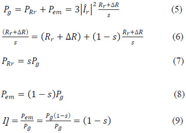
Motor by Variation of Rotor Resistance According to Fig. 1 the terminals of the rotor winding can be closed with additional resistances. If the resistance added to each phase of the rotor is 4R, there is increasing slip for which the maximum torque occurs, according with (4).

Fig. 1. Simplified diagram of the speed control to induction motor by varying the resistance of the rotor

The power passing from the stator to the rotor, air gap power Pg is given by (5). Through an appropriate mathematical manipulation of the rotor resistance carried by (6), obtains the components: (a) dissipated power in the rotor resistance PRr, (7), (b) resulting mechanical power on the motor shaft Pem, (8). From simplifications in particular neglecting losses in the stator resistance and the core loss, the yield of IM can be determined approximately by (9). Note that slip as well as losses increase with the increase in the rotor resistance and consequently there is a decrease in the yield of IM.
DESCRIPTION OF IRRIGATION PUMPING SYSTEM AND EQUIPMENT USED IN TEST
The Table 2 describes the parameters: electrical, hydraulic and geometric, for the pump set and installing the actual irrigation pump system under test.
Table. 2 TECHNICAL INDEXES OF THE IRRIGATION SYSTEM EVALUATED
|
Indexes |
Center pivot Medium pressure |
|
Design flow (m3h-1) Service pressure of the sprinklers (kPa) Rated power of the electric motor (HP) Number of poles of the electric motor (HP) Rotation of the electric motor (rpm) Rotation of the centrifugal pump Centrifugal pump model ETANORM Average slope of the land (%) length of suction pipe (m) Length of discharge piping (m) Drop in the discharge piping (m) Average pressure at the pump (kPa) Average pressure in the pivot (kPa) Pressure adjustment valves (kPa) |
52 140 25 2 3570 3570 G40-200 3,22 3,0 250 15 560 250 140 |
Fig. 2 illustrates a typical installation layout for center pivot irrigation, with representation and indication of major elements and nomenclature used in this work, where: SP is the suction pipe, ESB is output pump set, DP is the discharge piping, SF is the first sprinkler of lateral line pivot, SE is the last sprinkler of lateral line pivot, PRV is a pressure regulating valve.

Fig. 2. Typical scheme of installation for irrigation center pivot
To perform pressure measurements was used for analog gauges type gauges Bourdon metal and electrical transducers for digital measurement. To change the rotation of the pump was used a 25 HP variable frequency drive brand Gozuk.
Methodology
The procedures For mechanical and electrical measurements, with the pivot in normal operation, with the pump set at rated speed without speed control, and the pivot in normal operation with the pump set at variable speed controlled by VFD, the procedures were as described follows:
- Starting the electric motor taking it to its rated speed with the throttle valves fully open;
- With the pivot turning without stopping, at intervals of 5 minutes were recorded pressure measurements, active power and apparent power three-phase, voltages and currents, power factor, harmonic components of voltage and current and distortion rate total harmonic (THDV) e (THDI);
- Pressure measurements in the irrigation pump system in the following locations: output pump set, HESB, based on the sprinklers, end of the line side of the pivot, HSF e HSE, respectively.
A. Pump at Rated Speed
With the pivot in normal operation and pump in the rated speed, held pressure measurements: HESB, HSF and HSE. In the first half cycle of measurements the pivot toured the semi-circle of higher ground elevation and the second the lower elevations. Using data from these measurements is possible to developed curves of Fig. 3, allowing to make the comparison with the set value of the valves regulatory pressure, HPRV for analyzed positions.

Fig. 3. Pressures in the sprinklers, (HSF, HSE), in the rated speed pump compared to emph HPRV
In Fig. 3, can be observed that, for all positions of the circle irrigation, the pressures measured of the bases of the sprinklers are well above the rated pressure of the valves. The maximum pressure measured of the sprinklers was 266 kPa, ie, 90 % larger than 140 kPa, set point adjustment of the valves, HPRV. The minimum pressure measured at the sprinkler was 220 kPa, 57 % higher than the set pressure of the valves. In the Positions (0; 4200; 8400) seconds the pressure in the sprinklers equaled approximately 240 kPa.
B. Rotation Variable pump
In this section, the electromechanical drive motor is replaced by a VFD and the electrical analyzer was installed in the cable entry of the motor. With the pivot in normal operation and rotation of pump controlled by VFD, held measurements of pressure and electrical quantities such as the conditions of rated speed.
The rotation of the electric motor was kept just enough to ensure that all sprinklers pivot was pressure greater than HPRV. For this were constantly monitored pressures in HSF and HSE. For each set of measurements the load was recorded total head of the system, HESB, through pressure gauge at the outlet of the pump set.
Fig. 4 shows the pressure of the sprinklers on condition of speed control. Note that the minimum pressure will be 140 kPa and a maximum approximately 170 kPa. Under conditions of reduced speed, the maximum overpressure was 21 %, much smaller than 90 % observed in the condition of rated speed of the pump.

Fig. 4. Simulation of the pressure in the sprinklers, (HSF and HSE), for a complete revolution in the irrigated area with speed control
C. Measurement and Simulation of the Energy Saving to Drive with VFD and by Slip Control
The potential of the power savings, in that pivot, was assessed by comparing the results of measuring the electrical power to one full turn of pivot in irrigated area without speed control with:
- The simulation of the electric power consumed in the motor, using for it the relations of Rateaux under reduced rotational condition;
- The simulation of the electric power consumed in the motor, using the relations of Rateaux, taking into account, however, additional losses of yield in the conditions of speed control of motor by the resistances of the rotor (SC);
- Measurements of electrical power consumed by the speed of the motor controlled by a VFD.
Results
A. Pressures on Pump Output - Simulated and Measured Values
The application of control procedures already described, which resulted in the new working conditions of sprinklers shown in Fig. 4, resulted in a reduction of the total head of the system as seen in Fig. 5. In Fig. 5, HESB1 is a curve with measurements of the pressure at the outlet of the pump at nominal rotation, HESB2(SI) simulates the theoretical curve with the pressure values off the pump under reduced speed condition. HESB2(ME) is the pressure curve measured under the conditions of rotation reduced by the use of VFD.
Through Fig. 5, making the comparison between the simulated and measured values of the load gauge at the outlet of pump under reduced speed. It is demonstrated the validity of the theoretical method, based on the relations of Rateaux, to provide an estimate of potential energy conservation in pumping systems in general and irrigation pump systems with center pivot. For the system evaluated, it was shown that is substantially the amount of load shedding for the system as a whole. The average reduction of 100 kPa in HESB1, represents the possibility of relieving the load on the shaft of the electric motor in 18 %.

Fig. 5. Pressure pump with rated speed and reduced simulated and measured values
B. Power Curves - Simulated and Measured Values
Fig. 6 shows the results of electrical power for a complete cycle of the center pivot. The average electrical power measured under rated speed of pump was P1Me = 17.24 kW. The simulated power under conditions of variable speed using Rateaux relations was P2SIM = 13.22 kW. The measurement for variable speed with the use of a VFD, resulted in P2ME-INV = 13.08 kW. The simulated power for reduced speed by applying the power slip control technique in wound rotor motor was P2ME-SLIP = 14.29 kW. The percentage of energy savings for each case were, respectively: 23.27 %, 24.08 % e 17.05 %.

Fig. 6. Curves of active power to rated speed and reduced speed of the pump - measured and simulated values
C. Harmonic Study Results
The analysis of Fig. 7 indicates that the current harmonic components are significant, at the two extremes of the pump motor speed-reduction, using VFDs in the irrigated area.

Fig. 7. Current harmonic spectrum for two boundary conditions control the drive system
For the condition in which decreases in 8 %, the rotation of the pump in relation to nominal, -.⁄- = 0,92, the current harmonic components of the 5a and 7a order, representing 58 % and 34 %, respectively.
For the condition in which it reduces 4 % the rotation of the pump in relation to nominal -.⁄- = 0,96, the current harmonic components of the 5a and 7a order, representing 60 % and 30 %, respectively.
Harmonic distortion of currents in other orders are nonexistent or negligible.
Fig. 8 shows the percentage rates of total harmonic distortion of current and voltage, THDI and THDV, respectively, measured for the extreme variation of the motor speed.

Fig. 8. THDI e THDV for two control situations of the rotation of motor
For the condition n'/n = 0,92, the total harmonic distortion rates calculated were 74.2 % and 4.0 %, for THDI and THDV , respectively.
For the condition n'/n = 0,96, the total harmonic distortion rates calculated were 68,4 % and 4,6 %, for THDI and THDV , respectively.
See whether the data of Fig. 7 and Fig. 8, compared with the data of Tab. I, this is one of those cases where PCC = 80xPCONV, which has high harmonic components of current and voltage distortion worrying. Another problem observed in measurements is that the power factor showed low fp = 0.78.
Indices, individual and total harmonic distortion of currents or voltages, shown in Fig. 7 and Fig. 8, are the result of the use of VFDs for controlling the rotation of the pump. It is assumed negligible distortions produced in these waveforms produced by applying the technique of speed control slip (SC) in the induction motor rotor winding, bearing in mind that this technique does not change the waveform of voltage or frequency to produce the speed control.
Conclusions
Results showed great potential of energy savings by variable frequency drives in irrigation pump system. The percentage of energy savings can be even greater depending primarily on the slope of the terrain and in the use of well dimensioned motors.
In the typical case evaluated, the control performed by VFD applied to a three phase induction motor with cage rotor, pointed to a reduction in active power consumption of 24.08 %, whereas in control by slipping in wound rotor motors, the simulation indicated a reduction of 17.05 %. If the comparison is made between reductions in the consumption of apparent power, for this case, can be predicted that these ratios will be closer.
The option of using electric wound rotor induction motors, and the consequent possibility of using the control technique based on the insertion of resistances in the rotor may be a good option for rationalized use of electricity, specially in variable speed applications in rural facilities due to the fact that, in general, these facilities have small short circuit levels. In this situation the use of VFDs could cause considerable power quality problems.
For extreme conditions of variation of pump speed, the results presented high current and voltage harmonic distortion.