Variable Frequency Drive Harmonics
For the AC power line, the system (VFD + motor) is a non-linear load whose current include harmonics (frequency components multiples of the power line frequency). The characteristic harmonics generally produced by the rectifier are considered to be of order h = np±1 on the AC side, that is, on the power line (p is the number of pulses of the variable frequency drive and n =1,2,3).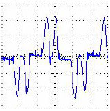 Thus, in the case of a 6 diode (6 pulses) bridge, the most pronounced generated harmonics are the 5th and the 7th ones, whose magnitudes may vary from 10% to 40% of the fundamental component, depending on the power line impedance. In the case of rectifying bridges of 12 pulses (12 diodes), the most harmful harmonics generated are the 11th and the 13th ones. The higher the order of the harmonic, the lower can be considered its magnitude, so higher order harmonics can be filtered more easily. As the majority of VFD manufacturers, Gozuk produces its low voltage standard variable frequency drives with 6-pulse rectifiers.
The power system harmonic distortion can be quantified by the THD (Total Harmonic Distortion), which is informed by the variable frequency drive manufacturer and is defined as:
Ah are the rms values of the non-fundamental harmonic components
A1 is the rms value of the fundamental component
The waveform above is the input measured current of a 6-pulse PWM variable frequency drive connected to a low impedance power grid.
Normative considerations about the harmonics
The NEMA Application Guide for variable frequency drive systems refers to IEEE Std.519 (1992), which recommends maximum THD levels for power systems ≤ 69 kV as per the tables presented next. This standard defines final installation values, so that each case deserves a particular evaluation. Data like the power line short-circuit impedance, points of common connection (PCC) of variable frequency drive and other loads, among others, influence on the recommended values.
The maximum harmonic current distortion recommended by IEEE-519 is given in terms of TDD (Total Demand Distortion) and depends on the ratio (ISC / IL), where:
ISC = maximum short-current current at PCC.
IL = maximum demand load current (fundamental frequency component) at PCC.
The documents mentioned from IEC, however, do not set limits for the harmonic distortion injected by variable frequency drives into the power line.
Line reactor / DC bus choke
Harmonic currents, which circulate through the power line impedances and depend on the rectifier input/output impedance values, cause harmonic voltage drops that distort the power supply voltage of the variable frequency drive and other loads connected to this line. These harmonic current and voltage distortions may increase the electrical losses in the installation, lowering the power factor and overheating components such as cables, transformers, capacitor banks, motors, etc.
The addition of a line reactor and/or a DC bus choke reduces the harmonic content of the current and increase the power factor. The DC bus choke has the advantage of not introducing a motor voltage drop but depending on the combination of its value with the power line impedance and the DC link capacitance values it may result in undesirable resonances within the overall system. On the other hand, the line reactor decreases the medium voltage of the intermediate circuit but attenuates more effectively power supply voltage transients. Besides that, it extends the semiconductors and the DC link capacitor bank lifetimes, as a result of the decrease of both the rms current of the rectifying diodes and the current ripple through the middle circuit capacitors.
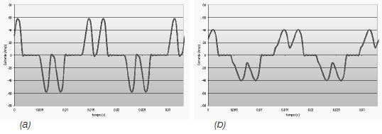
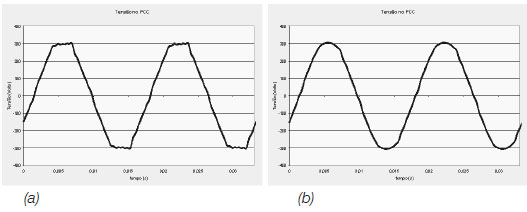
Current and voltage waveforms with (b) and without (a) line reactor. It can be seen that line reactors soften the peaks, thus reducing the harmonic content and the rms value of the input current. Additionally, diminution of the supply voltage waveform distortion is thereby caused.
A minimum line impedance that introduces a voltage drop from 1 to 2%, depending on the variable frequency drive size, is recommended in order to ensure the variable frequency drive lifetime. As rule of thumb, it is recommended to add a line reactor to the existing power supply impedance (including transformers and cables) so that a total voltage drop of 2 to 4% is achieved. This practice is considered to result in a good compromise between motor voltage drop, power factor improvement and harmonic current distortion reduction.
The value of the line reactor needed for the desired voltage drop to be obtained can be calculated as follows:
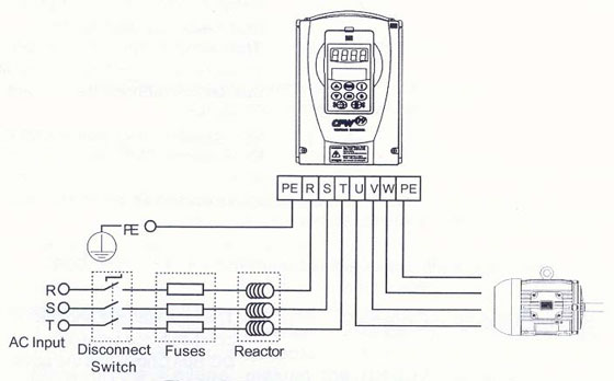
(a) Input line reactor connection
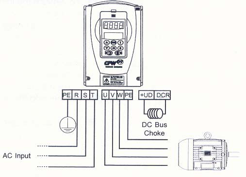
(b) DC bus choke connection
 Thus, in the case of a 6 diode (6 pulses) bridge, the most pronounced generated harmonics are the 5th and the 7th ones, whose magnitudes may vary from 10% to 40% of the fundamental component, depending on the power line impedance. In the case of rectifying bridges of 12 pulses (12 diodes), the most harmful harmonics generated are the 11th and the 13th ones. The higher the order of the harmonic, the lower can be considered its magnitude, so higher order harmonics can be filtered more easily. As the majority of VFD manufacturers, Gozuk produces its low voltage standard variable frequency drives with 6-pulse rectifiers.
The power system harmonic distortion can be quantified by the THD (Total Harmonic Distortion), which is informed by the variable frequency drive manufacturer and is defined as:
THD = √(∑∞h=2 (Ah/A1)2)Where
Ah are the rms values of the non-fundamental harmonic components
A1 is the rms value of the fundamental component
The waveform above is the input measured current of a 6-pulse PWM variable frequency drive connected to a low impedance power grid.
Normative considerations about the harmonics
The NEMA Application Guide for variable frequency drive systems refers to IEEE Std.519 (1992), which recommends maximum THD levels for power systems ≤ 69 kV as per the tables presented next. This standard defines final installation values, so that each case deserves a particular evaluation. Data like the power line short-circuit impedance, points of common connection (PCC) of variable frequency drive and other loads, among others, influence on the recommended values.
|
Voltage harmonics |
|
|
Even components |
3% |
|
Odd components |
3% |
|
THDvoltage |
5% |
The maximum harmonic current distortion recommended by IEEE-519 is given in terms of TDD (Total Demand Distortion) and depends on the ratio (ISC / IL), where:
ISC = maximum short-current current at PCC.
IL = maximum demand load current (fundamental frequency component) at PCC.
| Individual Odd Harmonics (Even harmonics are limited to 25% of the odd harmonic limits) | ||||||
| Maximum harmonic current distortion in percent of IL | ||||||
|
ISC/IL |
<11 |
11<h<17 |
17<h<23 |
23<h<35 |
35<h |
TDD |
|
<20 |
4 |
2 |
1.5 |
0.6 |
0.3 |
5 |
|
20<50 |
7 |
3.5 |
2.5 |
1 |
0.5 |
8 |
|
50<100 |
10 |
4.5 |
4 |
1.5 |
0.7 |
12 |
|
100<1000 |
12 |
5.5 |
5 |
2 |
1 |
15 |
|
>1000 |
15 |
7 |
6 |
2.5 |
1.4 |
20 |
The documents mentioned from IEC, however, do not set limits for the harmonic distortion injected by variable frequency drives into the power line.
Line reactor / DC bus choke
Harmonic currents, which circulate through the power line impedances and depend on the rectifier input/output impedance values, cause harmonic voltage drops that distort the power supply voltage of the variable frequency drive and other loads connected to this line. These harmonic current and voltage distortions may increase the electrical losses in the installation, lowering the power factor and overheating components such as cables, transformers, capacitor banks, motors, etc.
The addition of a line reactor and/or a DC bus choke reduces the harmonic content of the current and increase the power factor. The DC bus choke has the advantage of not introducing a motor voltage drop but depending on the combination of its value with the power line impedance and the DC link capacitance values it may result in undesirable resonances within the overall system. On the other hand, the line reactor decreases the medium voltage of the intermediate circuit but attenuates more effectively power supply voltage transients. Besides that, it extends the semiconductors and the DC link capacitor bank lifetimes, as a result of the decrease of both the rms current of the rectifying diodes and the current ripple through the middle circuit capacitors.


Current and voltage waveforms with (b) and without (a) line reactor. It can be seen that line reactors soften the peaks, thus reducing the harmonic content and the rms value of the input current. Additionally, diminution of the supply voltage waveform distortion is thereby caused.
A minimum line impedance that introduces a voltage drop from 1 to 2%, depending on the variable frequency drive size, is recommended in order to ensure the variable frequency drive lifetime. As rule of thumb, it is recommended to add a line reactor to the existing power supply impedance (including transformers and cables) so that a total voltage drop of 2 to 4% is achieved. This practice is considered to result in a good compromise between motor voltage drop, power factor improvement and harmonic current distortion reduction.
The value of the line reactor needed for the desired voltage drop to be obtained can be calculated as follows:
L = (voltage drop)% Vline / ((√3.2π)fline Irated) HThe (a) line reactor and (b) DC bus choke electrical installations are shown next.

(a) Input line reactor connection

(b) DC bus choke connection
You may also like:
The guy asked for suggestions on how to improve troubleshooting techniques. I mentioned this earlier as a "suggestion" for starters but the idea got lost in all the complaining and totally irrelevant responses ...
I have been designing power supplies for over 15 years now. We do mostly off line custom designs ranging from 50 to 500W. Often used in demanding environments such as offshore and shipping.
I think we are the ...
Many years ago we used to call this the "what ifs?". Part of the design phase is when we model what we think the system is meant to do. Just as important is how the system is meant to react when things are not ...
Synchronous motors generally offer more efficiency than induction ones, and hence in higher ratings (about 5000 hp and higher) they may be more cost effective considering Life Cycle Costs. The exact size of ...
DC drives with motor field control provide coordinated automatic armature & field voltage control for extended speed range & constant-horsepower applications. The motor is armature-voltage-controlled ...
 Gozuk Blog: all about electric motor control & drives industries development in energy saving applications.
Featured
Like pumps, fans consume significant electrical energy while serving several applications. In many plants, the VFDs (variable ...
 A frequency inverter controls AC motor speed. The frequency inverter converts the fixed supply frequency (60 Hz) to a ...
Motor starter (also known as soft starter, motor soft starter) is a electronic device integrates soft start, soft stop, ...
Soft starter allows the output voltage decreases gradually to achieve soft stop, in order to protect the equipment. Such as the ...
Soft Starter reduces electric motor starting current to 2-4 times during motor start up, reduces the impact to power grid during ...
In Discussion
Convert single phase motor wound aluminum wire to copper magnet wire
Should Automation Consultants align themselves to system vendors for marketing and discount gains?
Anyone making DC submersible pump motors?
How to optimize the power dissipated in a switching MOSFET transistor?
What is a Silent Pole Generator?
Solar PV installers
Reliance Auotmax PLC (with MB+ protocol) to communicate via TCP/IP?
An IEC standard is missing to enable cheaper products


