Variable frequency drive for refrigeration compressors
The minimization of energy consumption, a long service life-time and maximum availability and refrigeration security are to be achieved for both multi-stage compressor racks and fans of condensing units. The proposals made in the following refer to commercial refrigeration units at low and normal temperatures with refrigeration units with one up to three semi-hermetic reciprocating compressors of same size, with the compressor motors on a 3ph 400V/50 Hz supply.Saving Energy by Efficient Selection of Components
Energy-saving is essentially affected by optimizing the refrigeration thermodynamics by operating at maximum possible safe evaporation temperatures and minimum possible condensing temperatures. In the literature it can be read that raising the evaporation temperature by 1 K can save about 3.5 % of energy. Depending on the refrigerant, lowering the condensing temperature by 1 K can save about 3.3 % of energy.
Therefore optimum energy-saving control is aimed at providing the conditions for a maximum increase in evaporation temperature and lowest possible condensing temperature whilst maintaining the refrigeration capacity required. In order to achieve these goals, various planning aspects require special attention.
A good stepless control of compressor rack capacity requires the use of an intelligent variable frequency drive (VFD) specially designed for refrigeration use. An "Intelligent" variable frequency drive for refrigeration compressor use has various features which are not common with standard variable frequency drives for use in automation or industrial applications.
For example current control should be especially designed for refrigeration compressors: Currents above rated frequency are best avoided by frequency reduction, however only down to about 50 Hz. A reduction to less than 50 Hz would be counterproductive, as this would lower the refrigerant gas compressor cooling.
Further it is recommended to adapt maximum frequency to the refrigeration set point. A short-term exceeding of maximum compressor current is permissible, for example on restarting the rack after a power failure or extensive de-frosting.
It is also necessary that the minimum frequency is automatically adapted to the refrigeration operating point. This can be affected by evaluating the suction pressure, but also by evaluating the motor current of the refrigeration compressor.
An increase in motor current indicates that the kinetic energy in the moving parts of the compressor – dominated by the pistons - is not sufficient for a smooth pull-through at the point of highest torque. This is particularly critical with two-piston compressors, especially with transcritical CO2 compressors. Refrigeration variable frequency drive control should be intelligent enough to detect this problem and raise frequency, if necessary.
Reaching a high range of variation between maximum and minimum frequency is essential for optimum control performance with minimum deviation from the pressure setpoint. This can be made clear when considering the so-called Control Factor CF, which is defined as follows:
Control Factor CF = Variation of VsC refrigeration power / Fixed-speed Compressor (FsC) stepAssuming that the variable speed compressor and fixed speed compressor piston displacement is equal and no cylinder off-loading is activated, this formula can be reduced to:
VsC: Variable-speed Compressor
FsC: Fixed-speed Compressor.
Control Factor CF = (fmax [Hz] – fmin [Hz]) / 50 HzA control factor of > 80 % is to be aimed for. A control factor less than 80 % results in an unstable suction pressure with poor control performance of the expansion valves.
Some examples of field experience:
Use of a standard industrial variable frequency drive:
fmax: 60 HzUse of an intelligent variable frequency drive with refrigeration software (refrigeration variable frequency drive):
fmin: 30 Hz
Control Factor CF = (60 - 30) / 50 = 60 percent
Result: Poor control performance with large pressure disturbances.
fmax: 65 HzThis simple calculation shows the importance of a wide range of frequency achieved by intelligent refrigeration variable frequency drive control.
fmin: 25 Hz
Control Factor CF = (65 - 25) / 50 = 80 percent
Result: Good control performance with constant suction pressure and minimum energy consumption.
There are other good reasons for increasing the maximum frequency as high as possible:
- Reduced number of starts of the fixed speed compressor (FsC). Every start is a strain for the refrigeration compressor bearings and motor windings.
- Compared to conventional rack installations without variable frequency drives, the reduced number of starts extends compressor lifetime considerably.
- The refrigeration capacity available is approximately proportional to the frequency. Operation at higher frequencies means that a higher refrigeration capacity can be achieved with the same installation.

Fig. 1 Explanation of the Control Factor of a compressor rack
Energy saving with modern control technology
Special requirements for minimizing energy consumption with a high cooling quality and minimum dehumidification of stored goods will be discussed separately for both sides of the refrigeration cycle.
Requirements for the low-pressure side (evaporation):
In order to keep the suction pressure constant it is necessary to control the refrigeration capacity of the main frequency-controlled compressor without any delay on one hand, but also not too abruptly on the other hand. The main disturbances are caused by switching on and off temperature controlled cooling points. The begin and end of global defrosting intervals or starting up after a supply failure can cause high pressure deviations.
When starting and stopping fixed speed compressors (FsCs) in a multi-compressor rack, the suction pressure control has to decide whether the fixed speed compressors to be started are sufficient for the refrigeration performance required, or whether further compressors need to be started or stopped. We do not recommend the "dead zone" control principle; there are better algorithms to control the suction pressure.
The importance of increasing the evaporation temperature has already been described. There are various methods of increasing the evaporation temperature in accordance with various operating parameters:
- depending on the temperature inside the store
- depending on the humidity inside the store
- by analysing the actual compressor rack capacity (calculated in the internal compressor-rack control)
- by analyzing the switching of the temperature-controlled cooling points
- by analysing the superheat in the suction-line of the compressor rack. Sufficient superheat always has to be given priority over energy saving. When going below a preset superheat limit value (normally about 8 K), an increase in the evaporation temperature must be avoided.
Requirements for the high pressure side (condensation):
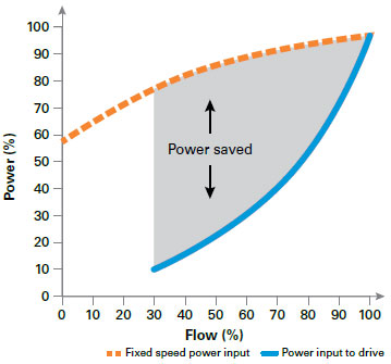
It may be assumed that the energy consumption of the condenser fans may reach about 10 to 15 percent of the total energy consumption of a refrigeration system. It is important to use fan motors of high efficiency, but in the following control measures and methods will be concentrated on.
Among these is maintaining constant condensation pressure by the variable-frequency control of the speed of the condenser fans. Switching fans on and off by step control is not well suited for this purpose, as an optimum energy-saving operation requires constant control over a wide range of capacity. This may be achieved by various means:
- Fan motors suitable for speed control using voltage control, normally by thyristor phase control. A typical range of capacity is between 30 and 100 %.
- New types of fan with integrated EC motors. A typical range of capacity is between 25 and 100 %.
- Three-phase fan motors, supplied by VFDs. A typical range of capacity is between -10 ... 0 ... 100 %t. When using VFDs even reverse operation is possible for compensation of convection losses during cold winter operation. However, other aspects must also be considered. Among these is the use of suitable all-pole motor filters in order to protect the fan motor windings against VFD voltage spikes.
Ambient temperature tamb: 35 °CThis calculation is valid for full-capacity operation.
Condenser temperature gradient tdelta: 12 K
Condensing temperature tc: 47 °C.
When working with 50 percent refrigeration capacity the following operating temperatures are recommended:
Ambient temperature tamb: 35 °CExample with Bitzer 2CC-4.2 compressor:
Condenser temperature gradient tdelta: 6 K
Condensing temperature tc: 41 °C.
te/tc: -10/47 °C; Q/P: 7.54/3.89 kWThere is an energy saving of 17 percent with the same refrigeration performance.
te/tc: -10/41 °C; Q/P: 8.50/3.65 kW
P: 3.65 * 7.54/8.50 = ca. 3.23 kW
Figure 2 shows a medium size refrigeration variable frequency drive. This variable frequency drive has four analog inputs for pressure and temperature as well as five output relays for compressor control. Some examples for diagnosis parameters and parameter settings for the refrigeration technicians are shown. More information is described in the following section.

Fig. 2: Refrigeration variable frequency drive, optimized for refrigeration with some typical settings.
Ease of use
It is important for the acceptance of energy-saving controllers such as refrigeration variable frequency drives that all essential refrigeration parameters are in the foreground. A typical VFD has about 1.000 electrical parameter settings. With some exceptions these parameters should all be pre-set and hidden to refrigeration technicians.
The control system displays the following diagnostic values and parameter settings for the refrigeration technician:
Diagnostic values:
- Suction gas superheat
- Compressor discharge temperature(s)
- Evaporating and condensing temperature (both at one glance)
- Evaporating and condensing pressure (both at one glance)
- Motor current and frequency (both at one glance)
- Number of compressors working
- Minimum evaporation pressure (Pump-down value): 2.5 bar (-16 °C)
- Setpoint 1 for suction pressure (Main set point): 3.3 bar (-10 °C)
- Setpoint 2 for suction pressure (For maximum energy-saving operation): 3.8 bar (- 6 °C)
- Maximum evaporation pressure (compressor limit value): 6.5 bar (+ 7,5 °C)
- Setpoint 1 for condensing pressure (winter operation): 13.1 bar (30 °C)
- Setpoint 2 for condensing pressure (energy recovery): 19.4 bar (45 °C)
- Maximum condensing pressure (compressor limit): 22.0 bar (50 °C)
- Refrigerant
- Frequency range of the VsC main compressor (min. and max. values according to compressor manufacturer)
- Maximum compressor current according to compressor manufacturer
- Dimensioning of temperature gradient delta t (K) of the condenser at maximum performance.
Selection of the compressor-rack arrangement
The following design objectives should be aimed for with the choice of the compressor-rack arrangement:
- Possibility of emergency operation without VFD control
- Swopping of fixed-speed compressors for optimum oil distribution
- Swopping of variable-speed compressors for equalization of wear and lifetime
- Minimizing the number of compressors starts to reach a long working life
- Single compressor systems: VFsC compressor + Refrigeration VFD + Emergency-Bypass
- Two compressor racks: VFsC1- + VFsC2 compressor + Refrigeration VFD / Automatic Swopping + Emergency-Bypass
- Three compressor racks: VsC compressor + Refrigeration VFD, automatic intelligent swopping of FsC1 + FsC2 compressors + Emergency-Bypass

Fig. 3 1x VFsC compressor

Fig. 4: 2 x VFsC compressors

Fig. 5: 1x VsC- + > 2x FsC compressor
The control system detects the difference in displacement of the compressors. Compressor swopping is only done at a high level of deviation. Swopping intervals are automatically adapted to operation conditions in order to keep the number of compressor starts as low as possible.
Refrigeration Security
In order to reach a highest possible level of refrigeration security, systems and arrangements with integrated redundancy of the refrigeration control are suggested. With the control system presented here the control is split between the intelligent refrigeration variable frequency drive and the external, but integrated intelligent control system.
The two systems monitor each other (with Watchdog and Handshake) and within a few seconds each one can take over emergency control of compressors and condenser fans independently, should any of the two systems fail.
Figure 6 shows a functional diagram of redundant control which has been successfully installed in many small supermarkets.

Fig. 6: Schematic diagram of a redundant control
Remote Monitoring and Alarm Processing
Signals for remote monitoring and alarm processing are provided by the standard RS 485 bus system using the Modbus RTU protocol. Essential operating parameters are available:
- Evaporation pressure
- Condensing pressure
- Trip messages
- Frequency and current of VsC compressor with the refrigeration VFD
- Number of compressors working
Controllers and complete electrical enclosures
The variable frequency drive technology is based on controlling equipment specially designed for electrical enclosures in refrigeration. It is aimed at standardizing the complete refrigeration controlling equipment by offering ready to- use standard electrical enclosures. This helps make installation easy and economical.
The simpler the electrical enclosure, the higher is its functional reliability and the faster trouble shooting can be done. If further electrical functional parts have to be integrated, there is enough space left to integrate them on a project basis.
Summary and future functions
The use of VFDs with integrated intelligence for the control of refrigeration compressors has been described in this article. Both, evaporating and condensing temperatures are controlled by one system at the same time. This presents an optimum configuration for high energy saving with good cooling quality.
Various control methods for increasing the service life time of refrigeration compressors have been described. The monitoring of suction superheat is an essential part of this. The principle of redundancy allows a high level of refrigeration security.
Up to now the VFD system has been successfully tested and used in commercial refrigeration. Current developments and test are planned for use in heat pump applications, chillers and air cooling systems.
Follow Gozuk on Facebook.