Variable frequency drive in fans system
Application introduction
Generally, the blowers in industrial equipments are driving by motor in constant speed operation, then adjusting the air flow by changing the fan inlet baffle opening degree. The biggest characteristic of the fan is the load torque is proportional to speed square, while the shaft power is proportional to speed cube. Therefore, energy-saving will be substantial if the fan's constant speed can be changed according to air flow demand by controlling motor speed.
Work Principle
Base on fluid mechanics, the motor output power (P) and air volume (Q), pressure (H) has following relationship:

P = K * H * Q / n
K is a constant, N is the efficiency.
The relationship with the speed N:
Q1/Q2 = N1/N2
H1/H2 = (N1/N2) 2
P1/P2 = (N1/N2) 3
In the graph, Curve 1 is the fan's characteristic of pressure H and flow Q under constant speed, curve 2 is the pipe network characteristic (valve opening to 100%). Suppose the fan is designed to work at maximum efficiency in point A, output air volume Q1 is 100%, the shaft power P1 = Q1 * H1 which is proportional to the area AH10Q1. According to the system process requirements, when the air volume decreases from Q1 to Q2 (e.g. 70%), if adjusting the regulator valve to achieve air volume decreased, it's equivalent to increase the pipe network resistance to make it change Curve 3, the system operation point change from the original point A to point B, we can see in the graph, the pressure increased, the shaft power P2 and area BH20Q2 are not decreased much.
If using variable frequency drive to adjust the motor speed, reduce the fan's speed from N1 to N2. According to the fan proportion formula, to draw curve 4 characteristic of the pressure H and flow Q under rotation speed N2, which we can see, air pressure H3 decrease significantly in the same air volume Q2 demand, and power P3 (area CH30Q2) also decrease significantly. The power savings △P = △HQ2 is proportional to area BH2H3C, the energy-saving effect is obviously.
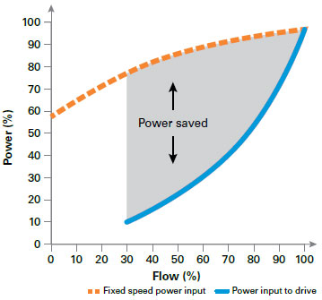
In theory, when the fan flow decrease to 80% and the speed drop to 80%, the shaft power will drop to 51% of the rated power; If the air flow decrease to 50%, the power P can will reduce to 13% of rated power. Of course, according to the actual working conditions, the actual energy savings can not reach to the theoretical value, but adopt variable frequency drive to control the air flow of the fan system, normally the saving rate can reach 20% - 50%, to meet the energy saving requirements.
Variable frequency drive wiring diagram

Benefits of variable speed controls
1. Achieve soft start and stop smoothly with little impact to the power grid and mechanical equipment.
2. Precise control and smooth speed adjusting, wide speed adjustment range and can realize stepless speed regulation.
3. Easy operation, decrease maintenance requirement and lower maintenance costs.
4. Strong protection function for the system, the variable frequency drives built-in overvoltage, overcurrent, undervoltage, overload, overheating and phase-loss protection, etc.